Having knowledge about NFV without understanding how Network Services/ VNF Forwarding Graphs are created, is like owning a car without knowing how to drive it.
“Network Service” (NS) holds importance in NFV as in the majority of cases, VNFs connect with one another to create services instead of working alone. Also, VNFs connect to create “VNF Forwarding Graphs”( VNF-FG).
So what is the difference between NS and VNF-FG?
But before that, why bother knowing about them?
Actually, they are important.
Take “Network Service” for example:
Network service ( NS) is what enables VNFs to combine and create many more functionalities which they are not able to do alone, NS is what an Orchestration system orchestrates.
And if you ever wonder how SDN plays in NFV environment, you must first understand how VNFs network with one another to create Network Services and VNF Forwarding Graphs.
Honestly, the information out there teaches you Network Service in a not very friendly manner. More specifically, in a Top-Down approach: starting from Network service and then going deeper.
This can become quite complex for a new learner.
On the other hand, I have concluded that the best way to teach Network Service and VNF-FG is not to start with them but rather build from their basic components and then lead to them.
This article does exactly that:
Virtual Links
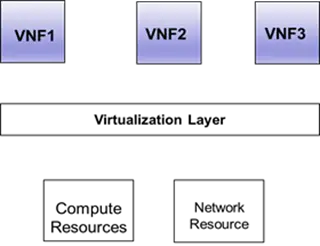
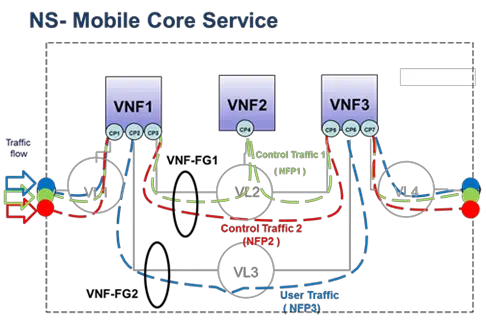
Below, you will see, three VNFs that need to connect to one another. Let us assume that these three VNFs are components of a Mobile Core network of an operator with each having different role (Understanding their role is not important here)
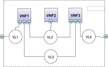
The first step is to create virtual links between the three VNFs.
Usually, a virtualization layer (hypervisor) will abstract the hardware resources under it enabling the VNFs to connect through virtual links, as shown below. Now why they are called virtual is because you do not see them, physical.
One simple example is that two VNFs might be present in one server and connect internally through a virtual link which you do not see.
Now you can see multiple virtual links between the VNFs. The virtual connectivity may be based on Layer 2 topology, for example, MEF E-Line, E-LAN or E-Tree services.
Network Forwarding Path( NFP)
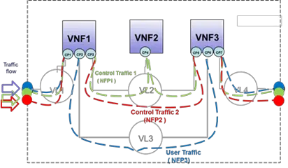
The next important concept is the Network Forwarding Path. Network Forwarding Path shows the path for the actual traffic flows on the virtual links.
Let’s say that in mobile core case, there is two kinds of traffic: Control Traffic and User Traffic.
In the following case, then, the Control traffic has furthur two paths and the User traffic has just one path:
NFP1- Forwarding path for “control traffic” that needs to pass through VNF1, VNF2, and VNF3 and uses VL2
NFP2- Forwarding path for “control traffic” that needs to pass through VNF1 and VNF3 (but not VNF2) but still uses VL2 (because of applying some policy that restricts it from VNF2)
NFP3- Forwarding path for “user traffic” that needs to pass through VNF1 and VNF3 but need to utilize VL3
VNF Forwarding Graph (VNF-FG)
Next very important concept is that of VNF Forwarding Graph (VNF-FG)
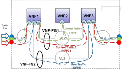
In the current example, the Control traffic will make one VNF-Forwarding Graph (VNF-FG) and the User traffic will make another VNF-FG. Think of forwarding paths as subsets of the VNF-FG. That is, one VNF-FG can have multiple forwarding paths.
The VNF-FG shows the graph of logical links connecting VNF nodes for the purpose of describing the traffic flow between these VNFs. In our case, there will be two different VNF-FGs owing to the involvement of different virtual links between the two paths.
VNF-FG1- VNF Forwarding Graph for Control Traffic
VNF-FG2-VNF Forwarding Graph for user traffic
Network Service (NS)
Once you grab the concept of NFP and VNF-FG, the concept of Network Service becomes very easy.
Think of Network Service as a layer above VNF-FG.
By definition, Network Service is a combination of the behavior of its constituent functional blocks, which can include individual VNFs, VNF Forwarding Graphs, and/or the infrastructure network.
Note! we are not just talking about the combination of certain VNFs but we are talking about a defined behavior from connecting certain VNFs together.
And the best way to know if a combination of VNFs forms a Network Service is to find out whether they have a Network Service Descriptor (NSD) associated with them. NSD template describes the deployment of network service including service topology (constituents VNFs, a virtual link, VNFFG) and associated service characteristics such as SLA.
Two or more Network Services can be combined to provide an end to end service like the following E2E service by combining Mobile RAN service with Mobile Core service.
So that’s it and here is the key takeaway from this blog and you should not forget:
Key Takeaway:
· E2E service is a combination of Network services.
· Network Service is a combination of VNF-FGs.
· VNF-FG is a combination of NFPs.
Question: Tell me your comments about anything in this blog. Did you find the concept of Network service and VNF-FG easy with the way it is described here? Please comment below.



Hi..thanks…i found this very useful..im new to sdn and nfv…keep up the good work abd please share more.
Would like to know about nfvi and mano also.
Thanks Dz, the best is still to come…..keep coming back
Hi Faisal,
I’ve request for NFV Mind Map but i didn’t get email confirmation, have tried few times. Do you mind to share and email to me. Thanks
Very useful!
HI Alok, Glad that you liked it.
Virtual Links, NFP, VNF-FG explained in very well manner . Simple brief explanation which can be understandable by anyone in networking industry.
Many thanks Faisal. Awaiting more and more in future with more practical approaches..
Can you bit more brief about use case as well with real time examples using NFV ?
Hello Abdul Ravoof,
Thank you. I am planning to explain some necessaary concepts before moving to real use cases. The real issue is that people are not clear about the basic concepts.
Good one… Made simple to understand…
Prabhu, thanks for visiting and glad that it met your expectation
Thank you, Faisal Khan.
Can I describe it this way?
– NFPs is a combination of two or more virtual links through which the actual flow happens.
– Virtual links connect the VNFs
I thought you could’ve included some lines about virtual links and VNFs in the key takeaways.
Hi Nithya,
thanks,
you nailed it correctly. Probably, I should add it to the take aways
thanks. Faisal
Hello Faisal,
Thanks for the good work. you did not describe connection points CP. according to my understanding virtual link is used to connect CPs
Regards,
Abbad
Hi Abbad, thanks, you nailed it.
Faisal,
You explain concepts in a very simple terms. Awesome blog! Thank you for taking time to post them for others benefits. Keep up the great effort!!
Best Regards, Venkat
Hi Venkat,
thank you for encouarging remarks.
Great Summary!
Thanks Nimer, Glad that you liked it
One question when we create VNF we define management ip and ports and internal ip’s and ports management is used to talk to external world and internal ip’s are used to talk within vnfc internally. Re you saying the vnffg has these information.
What you are saying is included in the virtual links information, whether the VNF talks internally or externally.
It is a fantastic example,so I am looking forward to apply a similar example to a transmission network elements(ADM,ROUTERS,LTE) like those of mobile elements.and I still have not an answer to my inquiry about the necessity of replacing the current transmission network elements(ROUTERs,ADMs,LTEs)with others compatible with NFV concepts from NFV appliances vendors for deploying NFV for first time so that it can respond to NFV MANO.
Regards.
Hi,
I would like to know more on the opensource based NFV testing tools and bench-marking. Couldn’t find proper guideline of NFV adoption and deployment. Perhaps you could guide and provide some references.
Thanks for your support and guidance.
Great article
Thanks Felix001 that you liked it
Would you provide me more information about the “control traffic” and “user traffic” in the Network Forwarding Path section?
Given one request, what is the relationship between its “control traffic” and “user traffic”, and what is the situation when SDN is introduced in NFV?
I am quit interested in this part, and any comments or reference materials is ok.
Hello BO, As mntioned in the article. The control traffic and user traffic was just examples to explain the concept. The control traffic can be any signalling traffic. The user traffic can be any traffic like voice or data. SDN can automate the creation of services and help in dynamically scaling up and down of the services. I am planning to write a more detailed description on the role of SDN. Please stay tuned.
Hi Faisal,
This post is awesome, you put it in a way that I can explain it to my non-techie sales partners. I’m a big data student, and I work for VoltDB who primarily sells into VNF applications, for me, this was a great way to share a visual understanding. Can’t wait to see those real-time use cases you were talking about! SDN/NFV go hand-in-hand from what I’ve seen, also interested to see your posts related to SDN.
Thanks!
Josh
Yes, Josh , good to know that you liked the articles.I am working on the SDN related articles. Stay tuned.
Dear Faisal,
First of all, I would like thank you very much for sharing very good article. To recap the basics of NFV , I read all your past articles once again, and attended some online courses. Initially, i read this article without revising concepts, it was not that clear. However, after revising concepts, very clear.
Dear Faisal,
You have neck for teaching… Kudos !!…. I discussed these points with my OSS team who is working on our orchestrator and they couldnt clarify the concept.
Two queries:
1) In lay terms Virtual Link behaves as Service chain ? We provision Open flow rules in vswitch to do the service chain in my company.
2) What i know is VL link can connect VNFs even without SDN controller ?
3) You mentioned about Layer 2 connectvity for VL. Its right but having E-line etc ? doesnt make sense in Datacenter environment. ideally it should be Vxlan
What are your thoughts on above
Thanks Mohit that you liked it.
1. Actual Virtual link is more related to the connectivity. You can defintely use openflow if you have SDN controller . A more appropriate analogy for service chain would be equating it to the network service.
2. Sure VL can connect without SDN controller. SDN controller is an option but gives you more flexibility and control of network resources.
2. In fact VL can be layer 2 or layer 3. Yes it can be VXLAN.
Hi Faisal,
The best article I’ve read about NS and VNFFG.
One question, why there are two VNFFGs in the example, rather than one VNFFG(including both the control plane and the user plane)? Or three VNFFG, each one only has one NFP?
Thanks,
Pascal
Thanks Pascal,
1. Why not one VNFFG.
Because the connectivity requirements for both are different, it is only logical to have two VNFFGs.
2. why not three VNFFGs.
You can have three VNFFGs, but then you will not appreciate the concept of NFPs. Here I want to show you that one VNFFG can have multiple NFPs. By using multiple NFPs, the VNFFG has the flexibility of routing the traffic through multiple paths without recreating a new VNFFG. it is just management simplicity.
HI Faisal,
I was actually waiting how will SDN be in the picture. Quick question though. In order to fulfill creation of Network Services, and NFV-O does the creation of an NS instance using the information based from NSDs and VNFDs where VNFFGs are defined. But during creation of the NS, are the IP details to actually provided the Network connectivity between the VNFs included when NFV-O commands creation of NS? Or is it that after creating the NS, The NFV-O then instructs the DC SDN Controller to do the actual service chain?
Hi Arjay,
Kindly get in touch through email to understand more on your question.
rgds,
Faisal
Hi Faisal,
Thanks for the wonderful overview of VNFFG and NFP.
I have some questions related to VL2. It seems that VNF1, VNF2, and VNF3 are connected to the same VL (VL #2). In NFP #1, the control traffic that VNF1 transmits will be received by VNF2 and VNF3. In NFP #2, the control traffic that VNF1 transmits will be received by VNF3. It is done via controlling the NfpRule, right?
Correct Joey !
Hi Faisa,
Good Day!!!
It is really kind document for beginner. Congrats to you for publishing your blog and educating us for this new technology.
Hi Faisal,
Its interesting topic and i found many blogs and articles on this but the way you have simplified it is awesome. I still have question how would you differentiate between Technical Service (VNF functionality) and Network Service ? From above explanation i understand that NS is combination of VNF FGs and VNFFG is combination of NSPs.
Thanks & Regards
Sandeep Kalley
Thanks Sandeep, NS is combination of VNFFG and VNFFG is combination of NFPs
Hello Faisal.
I would like to copy some of the diagrams present on that page, in an internal presentation I’ll do to some of my company colleagues (typically, the “Network Forwarding Path” one). I plan to mention your site as the origin of the diagram, but am I allowed to do so, and if so, do you have some specific copyright notice?
Thanks,
Daniel
Yes, please as long as you mention my website/my name
Fanstastic!! keep posting more and more about NFV and TOSCA templates
i have a doubt…VNF is nothing but when group of vms form a functionality, how these CP are related to VMs? does it mean each VM has one CP(connection point)?
Hi Faisal,
Great help and thanks for putting up there. I have seen this diagram elsewhere too, its better understood with your approach but still have a confusion.
VNF-FG1:NFP1 uses VL2 which in turn uses VNF1:CP3 -> VNF2:CP4 -> VNF3:CP5
VNF-FG1:NFP2 uses the path VNF1:CP3 -> VNF3:CP5 but the diagram does not show a corresponding VL for this. Shouldn’t there be another VL defined for this path?
If yes, that would imply that VL and NFP are actually the same thing.
If no, does it mean NFP may or may not be associated with VL but it (NFP) must be associated with CPs in case where a VL is not attached to it?
Many thanks..
NFP can be an abstraction above the VL. for example you create one VL and then you can create two overlays at top of it as separate NFPs. OK to make it simple. You can have the three VNFs connect through one layer 3 VPN which is your VL or underlay as shown in the diagram. Then you can give your NFV tenant access to this VPN so he can use it in whatever he likes. For example, he can create on top it two more logical links using encapsulation like VXLANs, thus keeping the two NFPs separate. However there is no hard and fast rule here and as suggested by you, You can create two NFPs on two seprate VLs also. ( which will be a different scenario than the one shown in the diagram)
Faisal
In the SFC diagram you depicted above ,there are only Service VNF’s that are chained .What i mean by Service VNF is Parental control , Video Optimization VNFs etc. If there are no routers VNF’s in the service chain how is L3 VPN Realized ? Can you please depict as a picture how is the L3VPN is realized for implementing the Virtual Links ?
The networking layer is not shown but of course you need a networking layer like switches or routers to have L2/L3 VPNs.
Hi Faisal, I have just joined your Blog, to fully understand the basic Operating Systems.
I must say that I have found the information shared on this platform very helpful indeed and has definitely put me in a better place of explaining to my Enterprise Customers in discussions pertaining to their Network Architecture going forward.
Diagrams, well orchestrated and definitions are clear and detailed. Definitely a follower going forward.
Thank you… 🙂
Thanks Mala. You made my day
This is good and nice explanation
Thank you, my doubt is cleared.
Thanks Mohamad for visiting and liking it
Hi Faisal… I have few doubt…
1. Can a vnffg or service chain between vnf and cnf?
2. NS (nsd) can be defined without vnffgd right? So in what situation that vnffgd is required in the nsd.
Please help to explain. Thanks.
Hi dz dz,
Sorry for replying late, as I had email issues.
I am not sure if I understood your question very well.
1. No
2. Can you elaborate more ?
Hi… we know that NS composes of VNF, VL, PNF, NFP, VNFFG. But from my observation the example of NS (tacker or osm for example) does not contain VNFFG… so if VNFFG is not includes in the NS, how exactly the VNFs interact and create the service chain? Seems without the VNFFG, VNFs defined in the NSD still can be established and communicate each other… I really hope you could help to answer this. Thanks